
Industrial Bldc Motor technology is reshaping motion control across factories, warehouses, and process plants. Unlike brushed motors, it uses permanent magnets and electronic commutation. The controller switches current through stator windings. Rotor movement follows the changing magnetic field.
This design removes mechanical brushes, reducing friction, sparking, and routine replacement. It also supports precise speed control. Hall sensors, encoders, or sensorless back-EMF detection can guide commutation. A conveyor may start smoothly under load, while a cooling fan can adjust speed within seconds. Small details matter. Poor tuning can still create vibration, heat, or audible switching noise.
The International Energy Agency’s Energy Efficiency 2023 analysis identifies electric motor systems as a major industrial efficiency opportunity. Its findings reinforce why engineers examine both motor efficiency and drive-system losses. Market research from Grand View Research and Fortune Business Insights also reports continued growth in the global brushless DC motor market, driven by automation, robotics, electric mobility, and energy-conscious equipment design. These reports vary in market boundaries and forecasts, so their figures should not be treated as identical. That limitation deserves attention.
This article explains what an Industrial Bldc Motor is and how it works. It connects electromagnetic principles with practical selection decisions, including torque, duty cycle, thermal management, ingress protection, and controller compatibility. Readers will also see where BLDC motors perform well, and where they may not. Efficiency is valuable. Reliability requires evidence. Testing under real load remains essential.
What Is an Industrial BLDC Motor and How Does It Work?
An industrial BLDC motor is a brushless direct-current motor designed for continuous, controlled operation. It replaces mechanical brushes with electronic commutation. This reduces contact wear and supports accurate speed control.
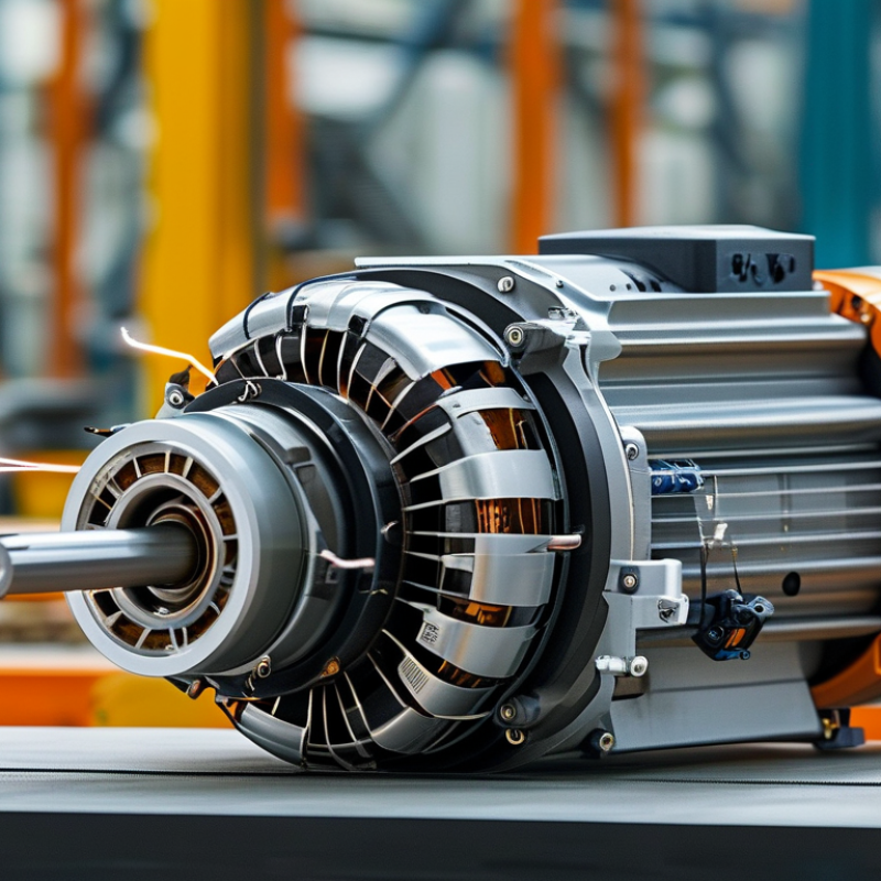
Its stator contains copper windings, while permanent magnets sit on the rotor. A controller reads rotor position through sensors or back-electromotive-force signals. It then switches current between winding phases. The changing magnetic field pulls the rotor forward. In a factory, this process may drive conveyors, pumps, robotic joints, or cooling fans.
Industrial BLDC motors usually offer high efficiency, compact size, low maintenance, and strong dynamic response. The International Energy Agency has reported that electric motor systems consume roughly half of global electricity. This makes motor efficiency important, although the figure covers many motor technologies, not BLDC units alone. The U.S. Department of Energy also emphasizes system-level efficiency, including controls, loads, and transmission components. A highly efficient motor can still waste energy when poorly matched.
Tips: Check rated torque, duty cycle, enclosure protection, and controller compatibility. Measure heat near the bearings and windings. Excessive temperature often reveals overload, weak cooling, or incorrect tuning. Sensorless control can reduce wiring, but it may perform poorly at very low speed. That trade-off deserves testing. Data sheets help, but real operating conditions decide performance.
| Data Dimension | Industrial BLDC Motor Data | Description and Engineering Significance |
|---|---|---|
| Definition | Electronically commutated permanent-magnet motor | A brushless DC motor uses permanent magnets on the rotor and electronically controlled current switching instead of mechanical brushes and a commutator. |
| Typical Industrial Power Range | Approximately 100 W to 100 kW | The practical range depends on the motor frame, cooling method, duty cycle, voltage, and application. Smaller units are common in automation, while larger versions support pumps, conveyors, and machine tools. |
| Common DC Bus Voltage | 24 V, 48 V, 72 V, 120 V, 240 V, and 310–325 V DC | The selected voltage must match the inverter, insulation system, safety requirements, and available power supply. Higher bus voltage generally reduces current for the same power output. |
| Motor Construction | Stationary stator with windings; rotating permanent-magnet rotor | The stator generates a rotating magnetic field, while rotor magnets follow that field to produce torque. This arrangement eliminates brush wear inside the motor. |
| Stator Core | Laminated electrical steel with copper windings | Laminations reduce eddy-current losses, while the distributed or concentrated windings create the electromagnetic field required for rotation. |
| Rotor Assembly | Permanent magnets mounted on or embedded in the rotor | Surface-mounted magnets are often used for compact, high-speed designs; embedded magnets can improve mechanical retention and field-weakening capability. |
| Electronic Commutation | Power inverter switches phase current electronically | A controller energizes the motor phases in sequence according to rotor position. Six-step trapezoidal commutation is common, while sinusoidal or field-oriented control provides smoother operation. |
| Position Feedback | Hall sensors, encoders, resolvers, or sensorless estimation | Feedback enables accurate commutation and speed control. Hall sensors are economical, while encoders and resolvers provide higher position resolution for demanding motion systems. |
| Typical Speed Range | Approximately 500 to 20,000 rpm | The actual speed range is determined by pole count, bearing design, rotor balance, back-EMF, load torque, and cooling capacity. High-speed designs require careful mechanical and thermal analysis. |
| Torque Characteristics | High starting torque; near-constant torque below base speed | With suitable current control, a BLDC motor can deliver strong acceleration and stable torque. Above base speed, field weakening may be used, subject to voltage and thermal limits. |
| Typical Efficiency | Approximately 80% to 95% at rated operating points | Efficiency varies with load, speed, winding resistance, iron loss, inverter loss, magnet design, and cooling. Peak efficiency does not occur at every operating condition. |
| Control Methods | Six-step control, sinusoidal control, and field-oriented control | Six-step control is relatively simple; sinusoidal and field-oriented control can reduce torque ripple and acoustic noise while improving dynamic performance. |
| Cooling Options | Natural convection, forced air, liquid cooling, or conduction cooling | Cooling removes copper, iron, bearing, and inverter-related heat. Continuous output is limited by the thermal path from the windings and housing to the environment. |
| Torque Ripple | Low to moderate, depending on design and control | Cogging torque, commutation strategy, slot-pole combination, current waveform, and position accuracy all influence vibration and speed uniformity. |
| Maintenance Requirement | Low routine maintenance; bearings and seals still require inspection | The absence of brushes removes a common wear component, but bearings, insulation, connectors, cooling paths, and feedback devices remain service items. |
| Industrial Advantages | High power density, fast response, compact size, and precise speed control | These characteristics make BLDC motors suitable for servo actuators, robotics, pumps, fans, conveyors, automated tooling, and other variable-speed equipment. |
| Key Design Limitations | Requires an electronic drive; magnets and electronics have temperature limits | System cost and complexity include the inverter, controller, feedback, electromagnetic compatibility measures, and protective functions. Excessive temperature can reduce magnet strength and insulation life. |
Note: Values shown are representative engineering ranges rather than universal ratings. Actual performance depends on motor geometry, drive settings, duty cycle, ambient conditions, and application requirements.



An exceptional record of quality and service for 35+ years.
© 2026 Excell Battery Co. All rights reserved.Privacy Statement